Potential of CO2-EOR associated with CCS in VietNam
Summary
CO2-EOR has a potential not only in enhancing oil recovery but also in CO2 storage. It is, however, necessary to understand the technical, operational and economic uncertainties by conducting a pilot test for applying CO2-EOR to actual oil fields. This paper describes the methods and procedures to design an inter-well CO2-EOR pilot test and discusses the potential of CO2-EOR in offshore fields, Vietnam.
We devised screening criteria in terms of saturations and reservoir pressure to select locations for pilot tests based on the reservoir model developed and calibrated with the actual field data. The number of pilot wells was determined to be one (1) injection well and two (2) production wells in order to estimate areal sweep efficiency during CO2 injection at a minimum cost. To confirm the effects of CO2-EOR, well interval, cumulative CO2 injection volume and duration were determined to be 300m, 2,000 tons and twoweeks, respectively. The oil production rate began to increase after 1 month from the beginning of the pilot test, and the gas production rate and the vapour phase CO2 mole fraction also began to increase at the same time. Then, the oil production rate reached the peak, which corresponds to oil bank, after 1.5 months from the beginning, and the effect of CO2-EOR was confirmed clearly. If oil saturation is high at the target reservoir, it would be difficult for confirming the oil bank clearly. In such case, pre-water injection before CO2 injection is conducted to reduce the oil saturation at the target reservoir.
In parallel, a CO2 procurement and a new platform were designed through the process optimisation study. Manufactured CO2 was selected as CO2 source for the pilot test due to easy availability andminimumcost. The packedmanufactured CO2 into tank containers was transported to the injection site by trucks and supply vessels. From a CO2 impact study, the potential risks related to corrosion and scale formation can bemanageable by suitable countermeasures such as corrosion resistant alloys (CRAs) and inhibitors.
We also estimated the CO2 volume for storage in the reservoir when CO2 injection was applied. Wefoundabouthalfofthe injected CO2 volume to remain in the reservoir at the normal operational conditions for CO2-EOR. Through this study we proposed a methodology to devise a pilot test plan of CO2-EOR in any offshore, remote oil field.
Key words: CO2-EOR, pre-water injection, CO2 injection.
1. Introduction
Enhanced oil recovery (EOR) by CO2 has a potential not only in enhancing oil recovery but also in CO2 storage. CO2 is a useful agent due to relatively high density and high solubility to crude oils. Because it is expected that sweep efficiency during CO2 injection is better than that in other gases i.e. hydrocarbon gases. It is also expected that miscible displacement by CO2 that enables to achieve high oil recovery is developed more readily in other gases.
In addition, CO2 is one of the greenhouse gasses that address global warming and climate changes. Many efforts have been made to reduce CO2 produced from industrial processes for a decade. Carbon stored underground is an important candidate for preventing CO2 gas from entering the atmosphere. The potent underground is oil and gas reservoirs. This is because the rock caps that are impermeable layer are integrity and the volume is large enough to be stored.
To meet incremental oil recovery and carbon storage, CO2-EOR associated with carbon capture and storage (CCS) has been proposed by many organisations. Similar to applications of CO2-EOR, it is necessary to understand the technical, operational and economic uncertainties by conducting a pilot test to actual oil fields.
The Vietnam Oil and Gas Group (PVN) and JOGMEC conducted an international joint study on a design of inter- well CO2-EOR pilot test at an oil field in Vietnam offshore from 2013 to 2015 in order to understand the applicability of CO2-EOR associated with CCS. The objectives of this study are to understand the CO2 injectivity, vertical sweep and areal sweep efficiency, incremental oil production, injected CO2 volume and cost/risks.
To design the CO2-EOR pilot test, not only subsurface study but also surface study is important to implement a proper and safe operation. When the injected CO2 is produced, potential risks related to CO2 such as corrosion and scale formation on the surface facilities will be increased. This paper describes the subsurface study including uncertainty analysis and countermeasure and the surface study including required CO2 procurement method, optimised surface facility design, and corrosion/ scale formation studies.
2. Subsurface study
Site selection
• Reservoir pressure > 2,600psi
• Oil saturation > 0.2
• Gas saturation = 0
The key factors to screen a pilot area for achieving the miscible displacement are the reservoir pressure in the pilot area. MMP of oil in this field was estimated to be 2,950psig based on the past laboratory studies such as slim-tube test and IFT measurement [1]. To observe the sufficient effects of CO2-EOR, the reservoir pressure during CO2 injection was set over 2,600psi based on the simulation study. A potential hydrocarbon zone was identified by a rule of thumb that porosity multiplied by the oil saturation is 0.05. We assume that the average porosity around the pilot test area is 0.25, thus, the oil saturation is estimated to be 0.2 as a screening criterion. If free gas is liberated in the reservoir, it leads to an undesirable oil displacement. Therefore, the gas saturation is set to 0. Some candidate areas for the pilot test were selected using the criteria.
Thereafter, a certain area was selected as the first option for the following reasons. The selected area is not close to the current producing areas and the large faults which may lead CO2 leaking from the reservoir, and the sufficient incremental oil was clearly estimated to confirm the effects of CO2-EOR based on the reservoir simulation results. Moreover, because the operator has a plan to develop the vicinity of this area, synergy between the development and the pilot test areas in terms of sharing the new platform has been expected.
Base case simulation
We designed a pilot test of CO2-EOR based on a reservoir simulation study. A pilot well configuration was selected to be one injection well and two production wells because of the minimum number of wells in order to understand CO2 areal sweep [4].
Some parameters such as well spacing, CO2 injection rate and total CO2 injection volume were determined based on the sensitivity analysis of reservoir simulation.
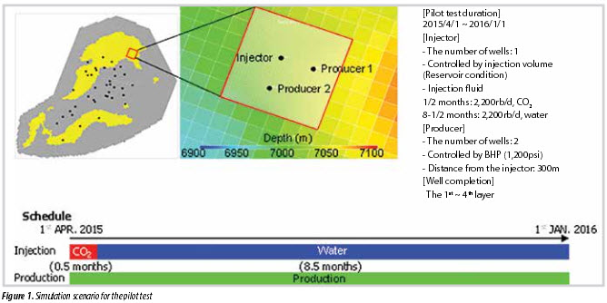
For determining these parameters, CO2 utilisation factor (= cumulative incremental oil volume by CO2- EOR/cumulative CO2 injection volume) was used as a performance index. The selected simulation settings for the pilot test are summarised in Figure 1. For maintaining the reservoir pressure, the BHP control value in the production wells is set so that the voidage replacement ratio should be one. To save the required CO2 volume for confirming the effects of CO2-EOR, both injection well and production wells were perforated in the limited zone of reservoir. The horizontal grid was refined to investigate the fluid advancement in detail.
Production profile predicted by reservoir simulation is shown in Figure 2. The oil production rate began to increase 1 month after the beginning of the pilot test. In addition, the gas production rate and the vapour phase CO2 mole fraction also began to increase at the same time. Then, the oil production rate reached the peak after 1.5 months from the beginning, and the effect of CO2-EOR can be confirmed clearly. As a result, the cumulative CO2 injection volume is 36,791Mscf (1,948 tons), and 52.8% amount of CO2 is stored in the reservoir (19,437Mscf, 1,029 tons). We also simulated the stored CO2 with various injection scenarios in the full field. The ratio of the stored CO2 to the injected CO2 during CO2-EOR is around 50% and 80% without and with recycling of produced CO2, respectively. Figure 3 shows the simulation results in the 2nd layer. CO2 sweeps mainly in this layer because the permeability is the highest in the other layers. Reservoir pressure near the injection well is higher than MMP during the simulation period. These simulation outputs also indicate practical aspects of CO2 flooding as follows. The interfacial tension in the CO2 swept area is very low (less than 1.0 dyne/cm). In addition, the oil viscosity in the CO2 swept area except for the vicinity of injection well becomes less than that in the unswept area. Oil saturation is decreased near the injection well, and an oil bank is seen at the downstream side of CO2 front. Residual oil saturation after the pilot test is small (less than 0.1) near the injection well.
Uncertainty analysis
The uncertainties of reservoir characteristic in the pilot test area are relatively high because it is an undeveloped area. For evaluating the uncertainties, based on the previous study [2, 3], sensitivity analysis using reservoir simulation and Monte Carlo simulation was conducted to address the key geological uncertainties which have significant impacts on the pilot performance, and make suitable countermeasures for a successful pilot implementation. In the sensitivity study, six geological parameters involving oil saturation, reservoir pressure, horizontal permeability, Kv/ Kh, Sorw and Sorg were selected. For each parameter, low and high cases were set based on the representative values from the reservoir characteristics. This sensitivity analysis was conducted by changing the parameter one by one while keeping the other parameters same as the base case. Figure 4 shows the sensitivity results for CO2 breakthrough
timing and cumulative production oil volume. The bar chart shows the difference over the base case. If the horizontal permeability or reservoir pressure is lower than the base case, the CO2 breakthrough timing delayed about 1 month. If the oil saturation is higher than the base case, the cumulative oil production volume increases significantly.
Monte Carlo simulation was conducted to estimate the range of pilot performance. In order to apply the Monte Carlo simulation for evaluating the range of the pilot performance, the response surface equation (RSE) and the probability distributions were constructed. The modelling of response surface equation for the cumulative oil production (COP) and the CO2 breakthrough timing (BTT) were conducted based on the regression of the sensitivity analysis results. The following equations were modelled as a function of geological uncertainties.
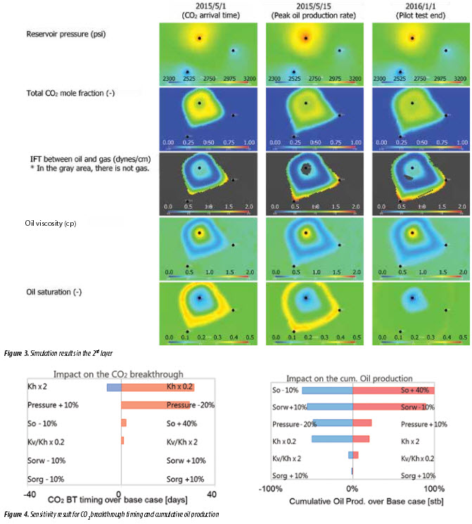
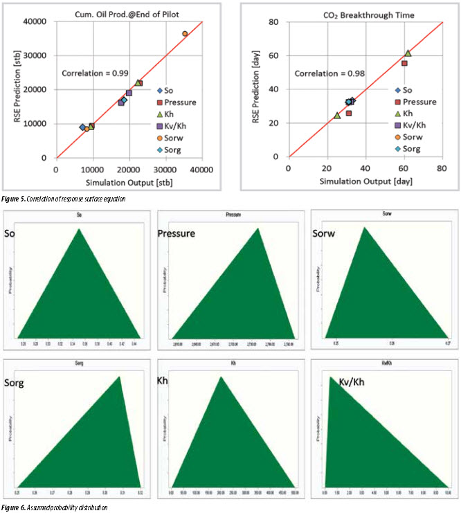
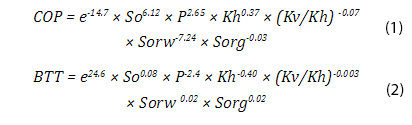
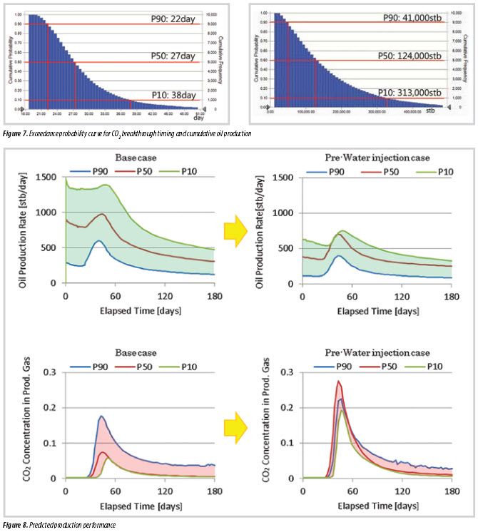
Figure 5 showsthecorrelationsbetweentheprediction results by RSE and the reservoir simulation output. The figure suggests that the predicted value by RSE is high correlation with that of the reservoir simulation.Figure 6 shows representative probability distributions of the geological parameters in the pilot area based on the simulation model. Figure 7 shows the output of Monte Carlo simulation for CO2 breakthrough timing and cumulative oil recovery for each probability. It is predicted that more than 41,000bbl oil will be recovered with 90% probability. In other words, the probability to be less than 41,000bbl is only 10%. Those results depend on the assumed probability distribution significantly. Table 1 shows the estimated geological parameters for each probability based on the most likely scenario.
The pilot production performance for each probability was predicted by reservoir simulation based on the estimated geological parameters. Figure 8 shows the oil production rate and CO2 concentration in production gas for P10, P50 and P90 cases, respectively. The left figures show the prediction results of the base
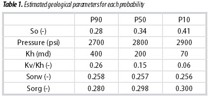
case. They indicate a wide range of the performance. It means that pilot production performance has a high uncertainty. Furthermore, it is found that the incremental oil production is not confirmed clearly in P10 case because of the shortage of CO2 injection volume over the large amount of oil in the reservoir.
Countermeasure for successful pilot test
If a large amount of CO2 can be prepared, we will confirm the oil bank readily even in P10 case. CO2 procurement volume is, however, limited in the offshore field.We consider pre-water injection before CO2 injection as an effective countermeasure for a successful pilot test implementation. The right figures in Figure 8 show the prediction results based on the base case scenario plus pre-water injection for 5 months. If pre-water injection is applied, not only the range of uncertainty decreases but also incremental oil by CO2-EOR is confirmed readily. If the actual oil saturation is higher than the expected oil saturation around the newly drilled pilot wells, the pre-water injection will be conducted for understanding the effects of CO2-EOR.
3. Surface study
CO2 procurement
We purchase liquefied CO2 which is the enough CO2 volume required for CO2-EOR pilot test from the supplier.
It is assumed that liquefied CO2 in the tank containers is transported to the offshore platform by trucks and vessels. Manufactured CO2 is filled up into the tank containers and carried by trucks to temporary storage area in the nearby port. The tank containers are moved to the supply vessels on the sea and transported to the pilot test area.
Surface facility design
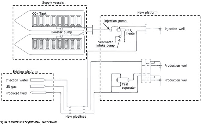
Because the pilot test area is undeveloped, it is necessary to build a new platform for the pilot test as well as treatment of production liquid, water injection and gas lift pipeline. As shown in Figure 9, liquid CO2 supplied from a supply vessel is send to the injection pump through the CO2 header, and injected into the reservoir from injection well via heater. Liquid CO2 heater is to prevent cracking of pipe and degradation of equipment materials. Injection water is supplied from the existing platform when water is injected after CO2 injection. The volume of produced gas and liquid from each production well is measured with the test separator.
CO2 breakthrough impact
The CO2 impact study for all the related facilities was conducted and divided into the following steps:
- Process simulation for all the related facilities;
- Corrosion and scaling formation estimation study for the related facilities;
- Material selection study based on process simulation and estimation results of corrosion and scaling formation.
Process simulation has been conducted to confirm how much CO2 is distributed to the related facilities. Corrosion rates and scaling formation potentials were estimated with a corrosion/electrolyte/scaling simulator, based on a “new fresh” carbon steel corroding surface.
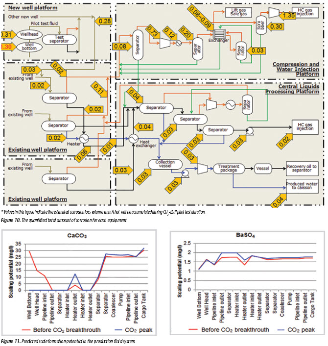
Corrosion
Figure 10 shows the total predicted corrosion amount for each production equipment/flowline for carbon steel, for the duration of the CO2-EOR project life. It was calculated by integrating the corrosion rate for each time. It shows that there is a very high total corrosion of 1.3mm of the production well tubulars downhole, with a reduced total corrosion of 0.31mm at the production wellhead once combined with lift gas, which further reduces to 0.28mm once combined
with the produced fluids from other well at the inlet to the flowline. The high predicted total corrosion depth for the well tubulars over the duration of the CO -EOR project for carbon steel is not deemed acceptable. It is noted that total corrosion of 1.35mm is predicted at the hydrocarbon gas compressor if the carbon steel is used. As high corrosion resistance alloy is used, the actual total amount of this equipment should become smaller and be negligible. Scaling
The predicted potential of BaSO4 and CaCO3 scales in the production system is presented in Figure 11.
This shows how the scale potential changes through the process, for the baseline simulation (before CO2 breakthrough) and the predicted peak breakthrough of CO2. Only the 2 cases have been plotted as the extreme cases. All of the simulated scale formation potentials for BaSO4 in the production process train are less than 2mg/L,

and so are manageable by suitable scale inhibitors. The breakthrough of CO2 into the production wells eliminates the scaling formation potential of CaCO3 in the front end of the production process train from the new well bottoms through to the inlet to the 1st heater inlet. This is probably due to the addition of CO2, shifting the pH of the produced fluids downwards (more acidic conditions) and therefore keeping the scaling ions in solution. With CO2 breakthrough, there is an increase in scaling potential of CaCO3 at the outlet of the 1st heater, but this level of CaCO3 scale is manageable by a suitable scale inhibitor. At the water outlet of the 2nd separator and all vessels downstream, there is very little change in the scaling potential for CaCO3, with only a 10% increase in the predicted amount of CaCO3 scale from the baseline simulation to the predicted peak breakthrough of CO2. This level of scale increase can easily be managed through the existing scale inhibitors used in this oil field.
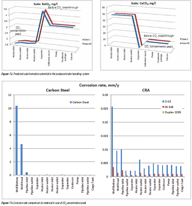
The predicted scale formation potential for the produced water handling system is presented by scale type in Figure 12. It does not change significantly from the baseline simulation to the predicted peak breakthrough of CO2. This level of scale in the produced water handling system can be easily managed through the existing scale inhibitors used in this oil field.
Material selection
Corrosion rate simulation was made using high corrosionresistancealloysasindicatedbelowtodetermine their suitability:
• 13Cr steel alloy;
• Stainless steel 316;
• Duplex stainless 2205;
The simulated corrosion rates across the process for these higher steel grades are presented in Figure 13. It is seen that all of the corrosion simulated high corrosion resistance alloys offer a vast improvement in the corrosion rate in the case of CO2 concentration peak. The corrosion rate at the well bottom for carbon steel at 10.37mm/year reduces to < 0.03mm/year when 13Cr steel alloy is used. This decrease in corrosion rate indicates the permissible corrosion limits that can be easily managed through the use of corrosion inhibitors. The corrosion rate can be further reduced through the use of either stainless steel 316 or duplex stainless 2205, as has been used in some oil fields to successfully mitigate corrosion. It should be noted that both stainless steel 316 and duplex stainless 2205 are very expensive for oil field process equipment.
Mitigation plan
The mitigation plan for corrosion risk and scale formation risk is summarised in Figure 14. It is quite evident that in the case of CO2 concentration peak the well completions in carbon steel are not appropriate. It is said that 13Cr steel alloy has typically been used for high CO2 gas wells. Stainless steel 316 appears to have a higher corrosion resistance than 13Cr steel alloy. It will, however, be prone to chloride stress corrosion cracking in higher temperature environments > 50°C in the presence of chloride ions. Duplex 2205 should provide even better corrosion resistance, but with very significant cost rise. The use of 13Cr steel alloy is suitable for the new production wells. It is effective to use also a variety of corrosion and scale inhibitors. As for test separator that will be installed on the pilot test platform, lining inside the separator by polymers such as polyethylene resin is desirable because fluid containing high CO2 concentration will flow into the separator although CO2 partial pressure decreases compared to wellhead and well bottom. In addition, it is necessary that regular pigging of the subsea flowlines and flaring of the associated produced gas at the pilot test platform reduce the corrosion potential in the topside process equipment and flowlines.
4. Conclusions
The CO2-EOR inter-well pilot test in the offshore oil field was designed to achieve the aim in all situations as follows;
• The number of pilot well is determined to be 1 injection well and 2 production wells because of the minimum number of wells in order to estimate CO2 areal effective countermeasure.
• To reduce the procurement cost of required CO2 for the pilot test, CO2 was determined to be secured from a CO2 manufactory.
• New platform was designed through the process optimisation study.
• There will be increased potential risk of corrosion and scale formation. The high predicted total corrosion depth for the well tubulars over the duration of the CO2- EOR project for carbon steel is not deemed acceptable, so the use of CRA’s in the production wells are essential. In addition, inside lining at the test separator, pigging and corrosion/scale inhibitors are necessary.
When the CO2-EOR pilot test will be planned in any oil field, it will be possible to make the test design with the same procedure as this study.
Acknowledgements
This study was implemented as a part of the joint study between the Vietnam Oil and Gas Group (PVN) and JOGMEC, financially supported by the Ministry of Economy, Trade and Industry (METI) in Japan. We would like to thank Petrovietnam and METI for providing permission to publish this paper.
References
1. Y.Kawahara, H.Mitsuishi, S.Takagi, H.Okabe, Nguyen Hai An, Nguyen Manh Hung, Phan Ngoc Trung, Y.Ueda. Comprehensive CO2-EOR study - Study on applicability of CO2-EOR to Rang Dong field - Part I: Laboratory study. Petrovietnam Journal. 2009; 6: p. 44 - 51. sweep efficiency. To achieve the aim of the pilot test, the well interval, cumulative CO2 injection volume and duration were determined to be 300m, 2,000 tons and 2 weeks, respectively, based on sensitivity study with reservoir simulation.
• We also simulated the stored CO2 with various injection scenarios in the full field. The ratio of the stored CO2 to the injected CO2 during CO2-EOR is around 50% and 80% without and with recycling of produced CO2, respectively.
• Uncertainty analysis indicates that there is a possibility the oil bank becomes smeared if the oil saturation is high. For confirming the effect of CO2-EOR clearly, pre-water injection before CO2 injection is an
2. D.Kuramoto. Uncertainty evaluation and history in concerning oil and natural gas reservoir simulation. Oil and Natural Gas Review. 2010; 44(2).
3. Ali Rawahi, Hafez H.Hafez, Arafat Al-Yafei, Saleem G.Ghori, Kevin L.Putney, Timonthy R.Matthews. Maximize the ultimate recovery by designing and optimising a CO2 miscible gas injection pilot in a giant carbonate oil reservoir, Abu Dhabi. International Petroleum Conference and Exhibition, Abu Dhabi, UAE. 11 - 14 November, 2012.
4. Gary F.Teletzke, Robert C.Wattenbarger, John R.Wilkinson. Enhanced oil recovery pilot testing best practices. SPE Reservoir Evaluation & Engineering. 2010; 13(1).